Trying a PS2 mod with a Pi3. Not much space in a PS2 Slim.
Fake DVD drive.
Flexible HDMI lead.
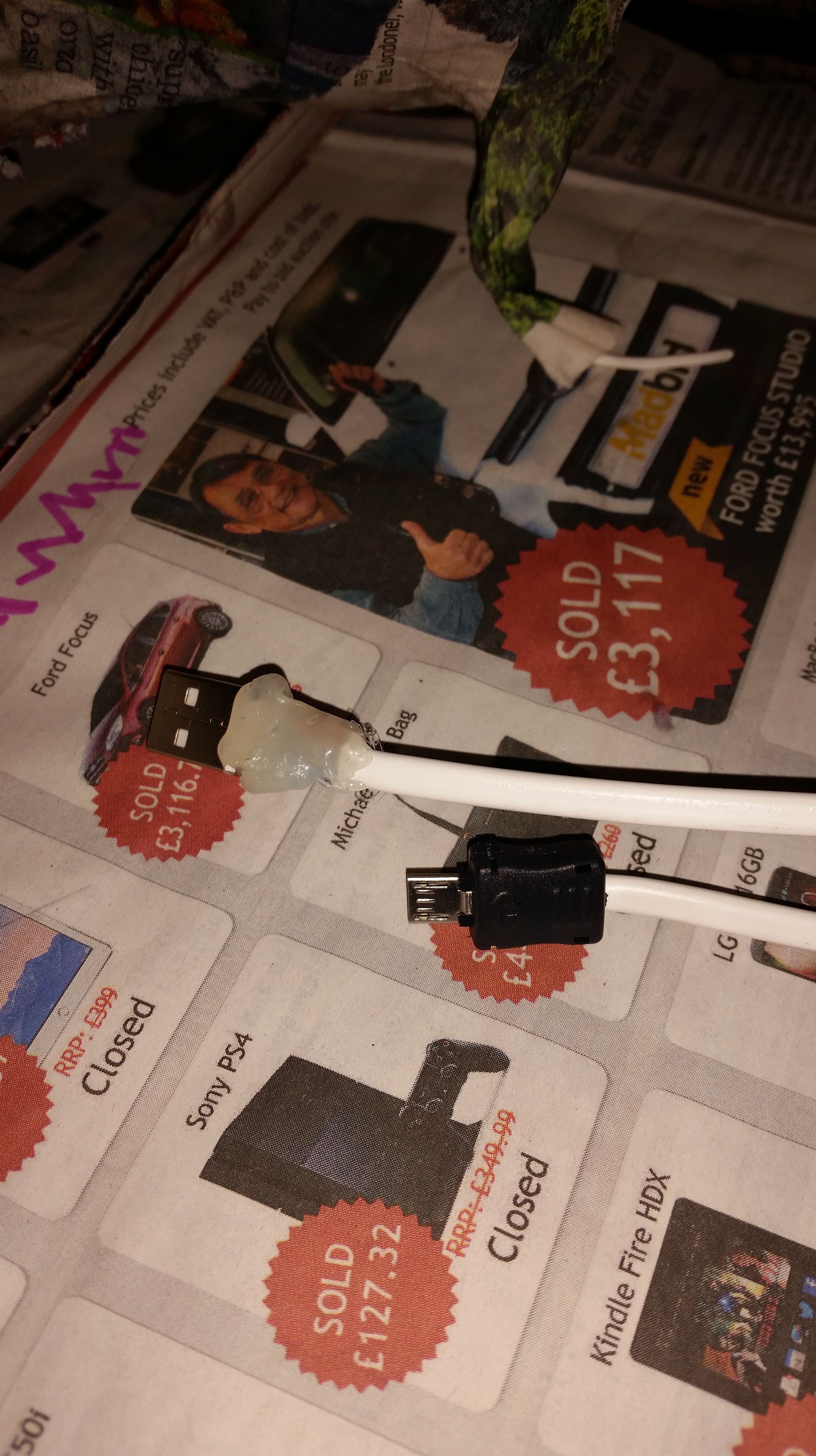
Stripped down USB cable.
Fake DVD drive made using parts stripped from the DVD player, plasticard and a bit of tinfoil.
Flexible HDMI lead connected to the Pi.
Stripped down USB cable to connect the hard drive to the Pi, Hard drive and Pi will each be powered by a seperate UBEC.
The ends of the USB cable have been made cable of sharper bends by carving away the flex protection with a stanley knife. this was necessary due to the limited space.
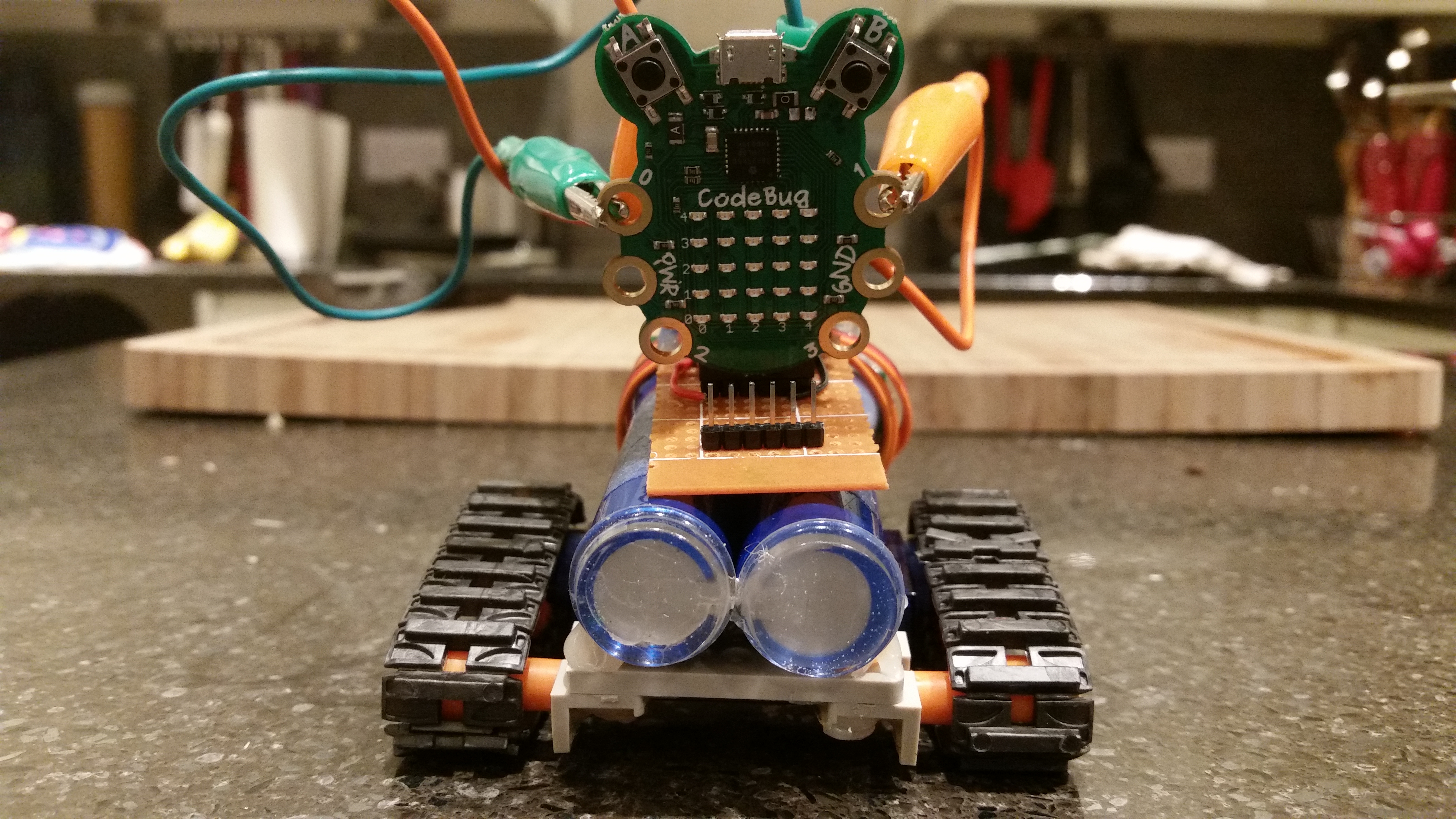
I’ve been making some progress with building my Codebuggy (Robot chassis for a codebug).
I’ve stripped a USB powerbank out of it’s shell and hot-glued it onto the chassis. I rotated the circuit board so that the USB socket was facing upward and I’ve covered it in hot-glue to make it safe for (and from) little fingers.
I made up an interface board to connect the servos and the codebug to the USB powerbank.
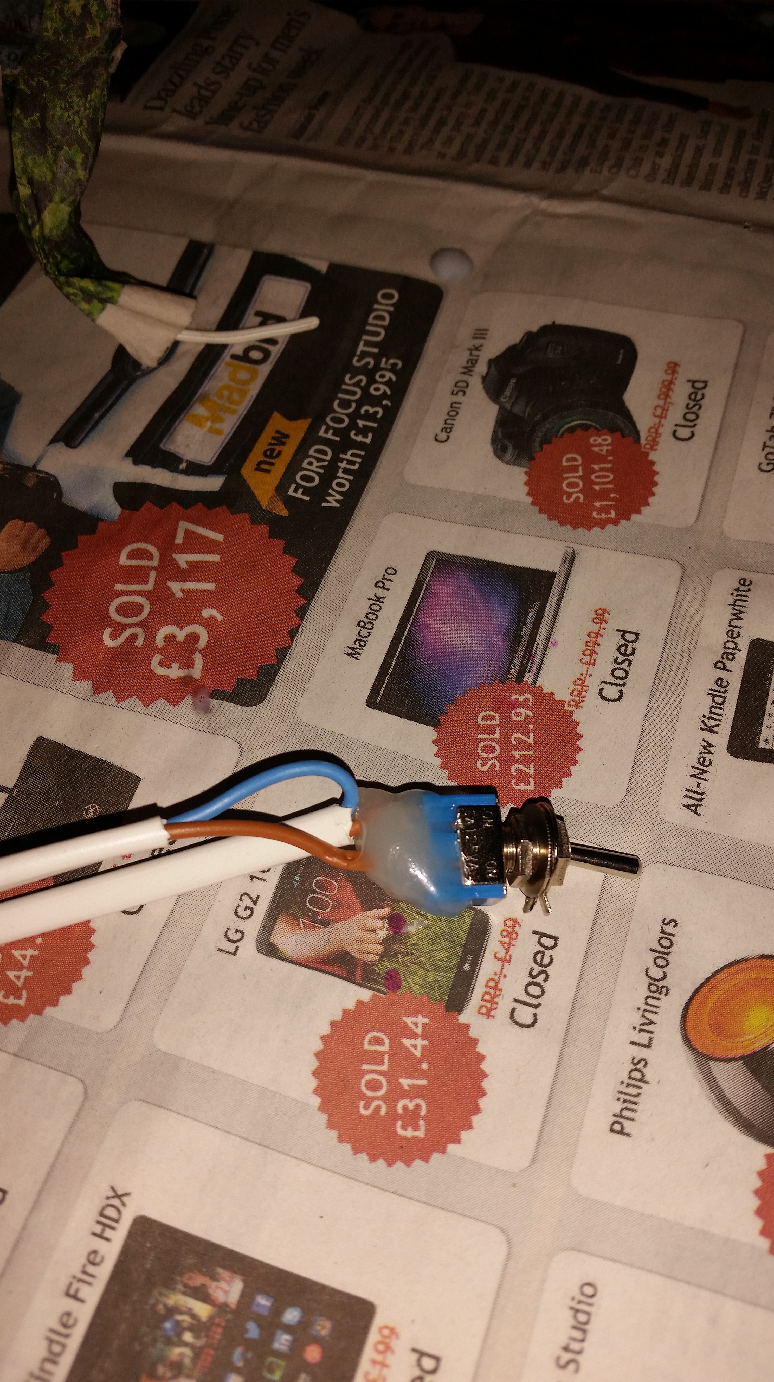
After a few hours I added a powerswitch to my interface board, making it easier to turn off the CodeBuggy (it runs off fairly quickly).
I’m having a problem adjusting the speed of the servos, they don’t respond correctly to changes in the program.
Still to do:
Replace experimenters kit croc clip leads with short connectors to codebug legs;
By the time my codebugs had arrived there was a lot of progress on the (unofficial) codebug forums with PiGraham writing code that would move servos. MikeR took this a stage further and built a codebuggy with continuous rotation servos and a chassis from an old robot project.
Reading the readme note was essential as the name and location of the library is critical to getting this to compile.
One issue to be aware of is that the readme suggested placing the files in sketchbook/Libraries whereas I found that it was required to be in sketchbook/libraries (lowercase L).
The example code compiled OK (once I’d figured out the correct file name and location).
sketchbook/libraries/Adafruit_PCD8544
sketchbook/libraries/Adafruit_GFX
I found a nice clear wiring scheme at duino4projects, which I’ve followed (but I’ve connected the backlight to a pin 9 for PWM so I can dim it). http://duino4projects.com/getting-nokia-5110-lcd-running-arduino/
Pictures of the wiring are less useful as there are different variants of this LCD board so the pin locations are relative.
I added some more female and male headers to my RasPiO Duino, in the prototyping area, for easier connections to peripherals.
I changed the male headers on the LCD for female ones (because I could only find my male dupont cables.
With a swift (OK, slow and painful) re-write of the display code we have a short countdown to….
I started with code for a countdown timer for 5110 LCD which I found on the Arduino forums:
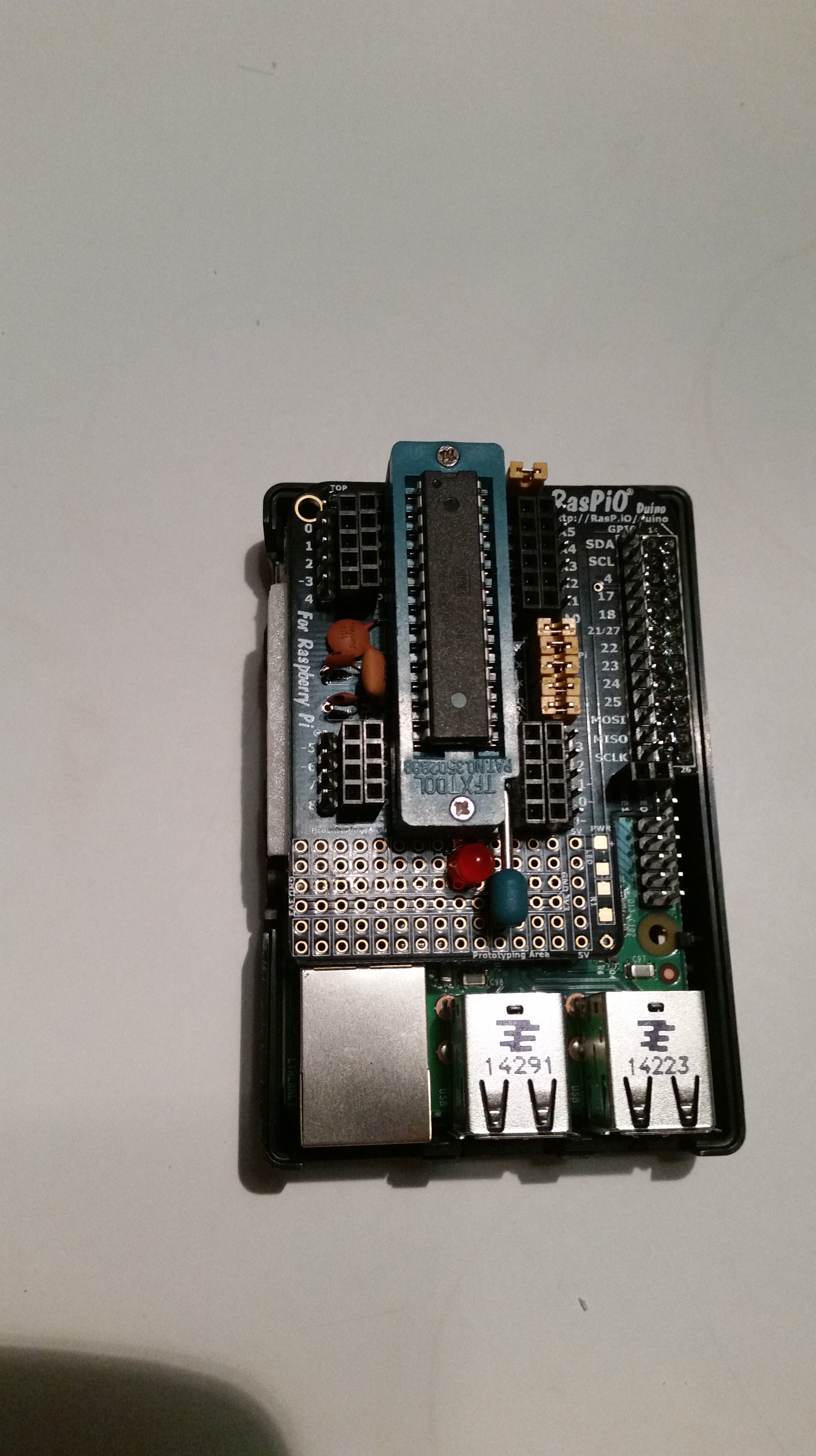
I backed the RasPiO duino kickstarter, I finally found an opportunity to solder together one of my boards last night.
I used a ZIF socket instead of the standard chip socket so I had to make a few modifications to the layout (most of which could have been avoided by using the optional surface mount components instead of through-hole).
I mounted the ZIF socket upside down so that it remains completely within the footprint of the Raspberry Pi.
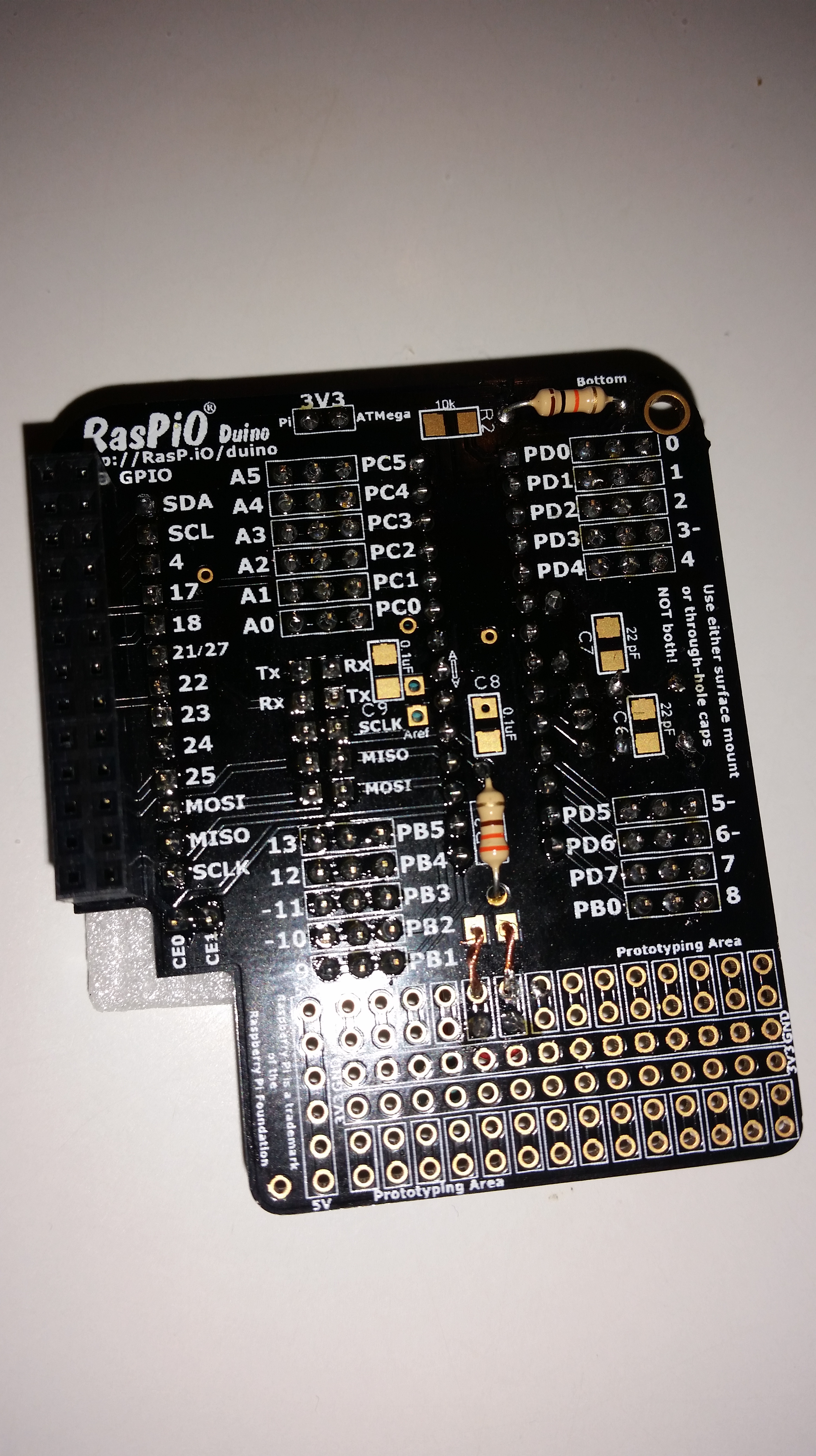
R1 would have obstructed the ZIF socket, so I mounted it on the bottom of the board.
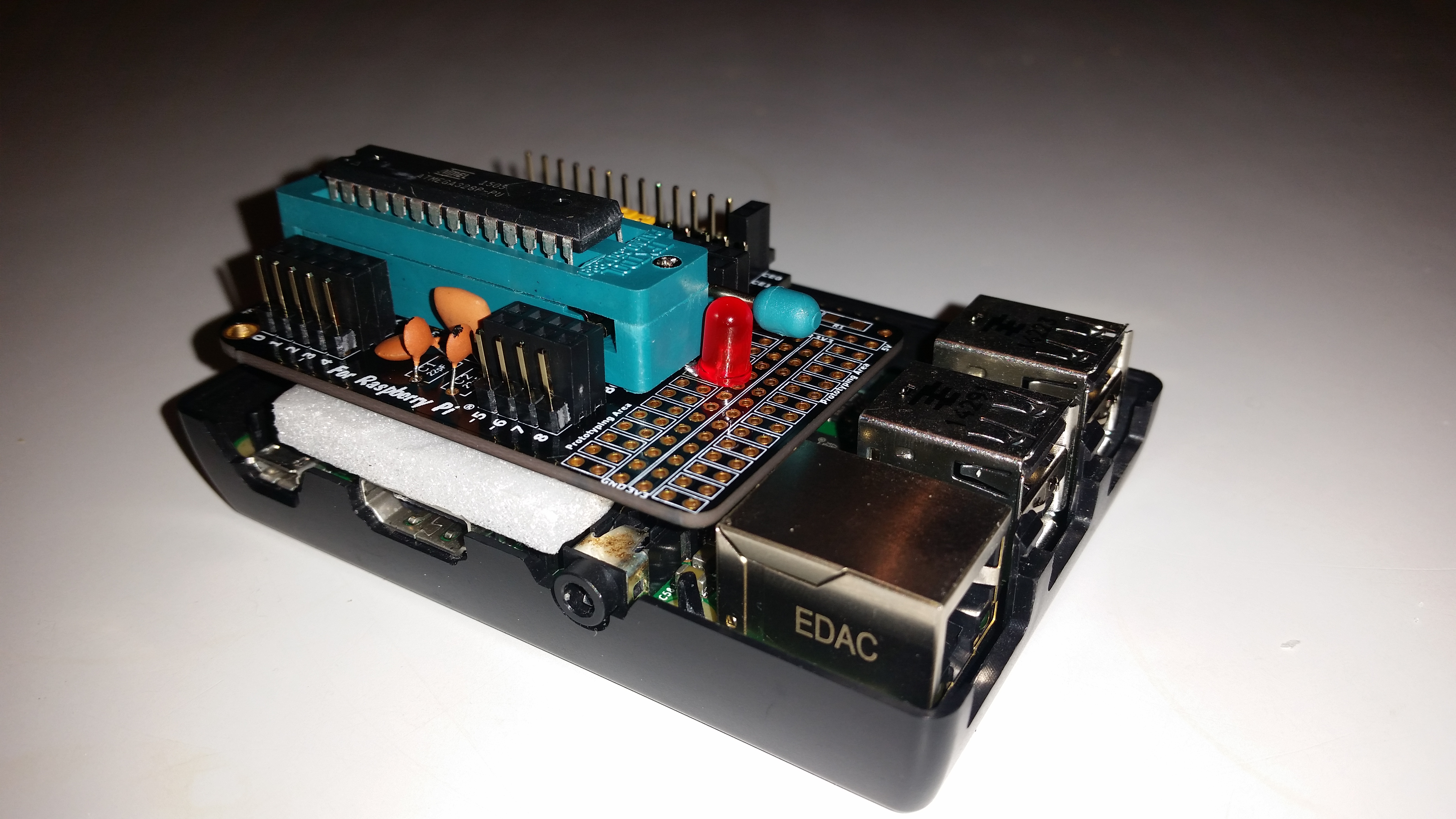
C3 was also under the ZIF socket, I left a bit of length on its legs and pushed it flat.
The resonator was very close to the side of the ZIF socket, a jaunty angle saved the day there.
The LED was completely obstructed, two very short links to the handy prototyping area (directly below) solved that issue.